


⚠️ AI-generated code. This project (firmware, tests, CI and documentation) was written by an AI model, Claude Fable 5.1 running in Claude Code, from a human specification and with human review and bench testing. Read the code before trusting it with anything that flies, and report anything odd in the issues.
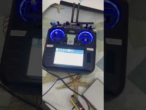
Click the image to watch the demo on YouTube.
Firmware for the ESP32-S3 that turns a wired USB HID joystick into a trainer input for EdgeTX radios such as the RadioMaster TX16S MKII. The ESP32-S3 acts as a native USB host, decodes the joystick's HID reports and emits SBUS and CPPM at the same time on two GPIOs.
USB HID joystick  (e.g. Microsoft SideWinder Force Feedback 2, 045E:001B)
      │  USB full speed
      ▼
ESP32-S3 native USB host  ──►  HID report descriptor parser  ──►  normalised axes/buttons/hat
      │
      ▼
configurable channel mapping (source, invert, dead band, expo, end points, trim, failsafe)
      ├──►  SBUS  (UART1, 100000 8E2, hardware inverted)  ──►  GPIO 17
      └──►  CPPM  (RMT peripheral, no bit-banging)        ──►  GPIO 18
Force feedback is used for one thing: the bridge creates the centring spring on the joystick (a USB HID PID effect; without it a SideWinder is loose) and offers a vibration test. Game-style effects are out of scope.
Status: flown. The firmware at commit
59b4e3c(release v0.9.0 plus documentation updates) was used for a first real flight on 2026-10-24 with a SideWinder Force Feedback 2, an ESP32-S3-DevKitC-1 and a RadioMaster TX16S MKII running EdgeTX, SBUS on the radio's AUX serial port (Master/Serial): it worked without issues. The CPPM output on the trainer jack and the SBUS input on the module bay S.PORT pin are implemented but not yet tested on the radio, and the force feedback added afterwards still needs its first bench test. See Tested setups.
- Features
- Hardware
- Wiring to the TX16S MKII
- EdgeTX setup
- Building, flashing, testing
- Configuration
- Architecture
- Design decisions
- Limitations and roadmap
- Native USB host on the ESP32-S3 (ESP-IDF
usbhost library + Espressifusb_host_hidclass driver). No Bluetooth, no external USB host shield. - Force feedback centring spring for USB HID PID joysticks (SideWinder Force Feedback 2): the stick returns to centre by itself; strength and gain are configurable, plus a vibration test.
- Generic HID joystick support: the report descriptor is parsed at run time, so any joystick or gamepad that follows the HID usage tables works (X/Y/Z/Rx/Ry/Rz/slider/dial/wheel, throttle/rudder/accelerator/brake, hat switch, up to 32 buttons, report IDs, array buttons). The SideWinder Force Feedback 2 descriptor is part of the test suite.
- SBUS and CPPM simultaneously, each on its own GPIO, each individually configurable (period, polarity, number of channels, pulse width, frame length).
- CPPM generated by the RMT peripheral: the whole frame is handed to the hardware, timing does not depend on interrupt latency or on the USB task.
- SBUS inversion in hardware (UART TX inverter of the ESP32): no external transistor.
- Safe disconnection handling: on USB unplug the outputs go to a configurable failsafe (stop, hold, preset). By default they simply stop, which makes EdgeTX hand control back to the instructor's sticks within one second.
- Everything configurable at run time from a serial console and persisted in NVS:
GPIOs, mapping per channel, inversion, dead band, expo, end points, trims, failsafe values,
timings. Compile-time defaults are
-Dflags inplatformio.ini. - PlatformIO project with host-side unit tests (
pio test -e native) and a GitHub Actions pipeline (format check, tests, firmware build with downloadable artifacts).
| Item | Notes |
|---|---|
| ESP32-S3 dev board | Tested build target: esp32-s3-devkitc-1. Any ESP32-S3 board that exposes the native USB pins (GPIO19/20) works. Other chips: see docs/hardware-options.md (short version: ESP32-S2 yes, RP2040/RP2350 and ESP32-C3/C5 no). |
| JR bay module (prototype PCB) | A 22 x 62 mm board that plugs into the radio's module bay: ESP32-S3-WROOM-1, USB-A host port, USB-C console, 2S buck, SBUS/CPPM on the bay pins and an AUX header. KiCad project, Gerbers, BOM and a printable case in hardware/. Untested as of this release. |
| USB OTG cable with power input | Micro-USB (USB-C on some boards) OTG host plug + USB-A female for the joystick + a power input. See Powering the joystick: a plain OTG adapter is not enough on the DevKitC-1. |
| USB-to-UART link | The DevKitC-1's second connector labelled "UART"; used for flashing, logs and the configuration console. |
| 3.5 mm TRS plug | For the CPPM trainer input of the radio. |
| Dupont wires / JR pins | For the SBUS input (module bay S.PORT pin or AUX serial connector). |
The joystick must receive 5 V on VBUS from the host connector, and the ESP32-S3-DevKitC-1 cannot provide it by design: in the board schematic the VBUS pin of the native "USB" connector (J4) reaches the 5 V rail only through the Schottky diode D7, oriented from the connector into the board. The board can be powered from that port, but 5 V never flows out to a connected device, and there is no jumper or solder pad to change that. The firmware therefore enumerates nothing until VBUS is supplied in one of these ways:
- OTG Y-cable with power input (no soldering, recommended): a "micro-USB OTG host + power" cable. Its power socket takes 5 V from a USB charger, its USB-A socket feeds the joystick, and the same 5 V also enters the board through D7, so one supply powers everything while the UART port stays free for the console.
- Wire from the header pin
5Vto the VBUS pad of J4, or a solder bridge across D7. The board is then powered from the UART port or the5Vpin. With D7 bridged, never connect a PC to the native port while the board is powered from another source. - USB-A female breakout on the header: VBUS to
5V, GND toGND, D+ toGPIO20, D- toGPIO19, short twisted wires; the on-board connector is left unused.
The SideWinder FFB2 declares 100 mA over USB; it also has its own mains power supply for the motors, which must be connected for the stick to enumerate reliably.
Power the ESP32 from its UART/USB connector or from a clean 5 V source. Do not power it from
the radio's module bay BATT pin: that pin carries the battery voltage (up to 8.4 V).
| Signal | GPIO | Level | Change with |
|---|---|---|---|
| SBUS out | 17 | 3.3 V, idle low (inverted UART, standard SBUS) | set sbus.gpio N, set sbus.inverted 0/1 |
| CPPM out | 18 | 3.3 V, idle high, 300 µs low pulses | set cppm.gpio N, set cppm.inverted 0/1 |
| Status LED | none (-1) | active high | set led.gpio N |
| USB host D-/D+ | 19 / 20 | native USB | fixed |
| Console | UART0 (USB-UART bridge) | 115200 8N1 | fixed |
Avoid the strapping pins (0, 3, 45, 46), the flash/PSRAM pins (26-37 on modules with octal PSRAM) and 19/20 (USB). 3.3 V logic is enough for the STM32 inputs of the TX16S (they are 5 V tolerant, threshold about 2 V).
EdgeTX offers several trainer input modes. The ones usable with this bridge on a TX16S are:
| EdgeTX trainer mode | Physical input on the TX16S | Signal to send | Bridge setting |
|---|---|---|---|
| Master/Jack | 3.5 mm trainer jack on the back | CPPM | cppm.* defaults |
| Master/SBUS Module | external module bay, S.PORT pin (with External RF off) | SBUS, standard polarity (idle low) | sbus.inverted 1 (default) |
| Master/Serial | AUX1 (or AUX2) serial port configured as "SBUS Trainer" | SBUS, UART polarity (idle high) | sbus.inverted 0 |
| Master/CPPM Module | module bay HEARTBEAT pin | – | does not work on the TX16S/MKII (hardware issue, EdgeTX issue #4672) |
EdgeTX uses one trainer mode per model, so in practice you connect either the CPPM output or the SBUS output to the radio. Both are generated all the time; the other one is free for a second radio or a simulator dongle.
| Path | Radio side | Bridge side | Result |
|---|---|---|---|
| SBUS on AUX serial port | TX16S MKII, EdgeTX, AUX port on the bottom set to SBUS Trainer, model in Master/Serial; external bay occupied by an ExpressLRS module, internal multi-protocol module |
GPIO17 → AUX RX, GND → GND, set sbus.inverted 0 + save |
Works, flown. Bench-verified on 2026-09-20, first flight on 2026-10-24 with the firmware of commit 59b4e3c: the model was flown from the joystick through the trainer function without any issue. |
| CPPM on the trainer jack | Master/Jack |
GPIO18 → tip, GND → sleeve | Not yet tested (no jack at hand). Encoder timing is covered by unit tests against EdgeTX's decoder rules. |
| SBUS on module bay S.PORT | Master/SBUS Module, External RF off |
GPIO17 → pin 5, sbus.inverted 1 |
Not yet tested (bay occupied by the ELRS module). |
| Force feedback (centring spring) | – | SideWinder FFB2 with its mains adapter connected | Implemented after the first flight, not yet bench-tested: the report sequence is verified against the real descriptor in the unit tests only. See Force feedback. |
Lessons learned during the first bring-up:
- The DevKitC-1 does not power the joystick from its native USB port; a powered OTG Y-cable fixed it (see Powering the joystick).
- The AUX port wants UART polarity: with the default
sbus.inverted 1the radio sees nothing at all.set sbus.inverted 0takes effect immediately, thensave. - With the default
failsafe.mode stopnothing is emitted until the joystick sends its first report; the SideWinder only reports on change, so move the stick once and checkstatus.
ESP32-S3 GPIO18 ──────► tip    (PPM)      3.5 mm TRS plug
ESP32-S3 GND    ──────► sleeve (GND)
                        ring   not connected
This follows the OpenTX/EdgeTX convention (PPM on the tip, ground on the sleeve, ring unused). The original TX16S used a 4-pole socket, the MKII a standard 3-pole TRS socket. If your radio does not see the signal, verify the socket with a multimeter (sleeve = ground) before assuming a firmware problem. EdgeTX measures rising edge to rising edge, accepts 800-2200 µs per channel and needs a sync gap of 4-19 ms; the encoder keeps every frame inside that window by design.
JR module bay (top to bottom):  1 PPM   2 HEARTBEAT   3 BATT   4 GND   5 S.PORT
ESP32-S3 GPIO17 ──────► pin 5 (S.PORT)
ESP32-S3 GND    ──────► pin 4 (GND)
Keep sbus.inverted = 1 (standard SBUS). Set the model's External RF to OFF or the mode is
not offered. Never connect pin 3 (BATT) to the ESP32.
ESP32-S3 GPIO17 ──────► AUX port RX pin (the radio's receive line)
ESP32-S3 GND    ──────► AUX port GND
                        AUX port 5V and TX left unconnected
Set sbus.inverted = 0 (the STM32F4 in the TX16S cannot invert its UART input, so the AUX
port expects idle-high UART polarity) and save. Do not exceed 3.3 V on the AUX pins. This path
works with any module in the external bay (it was verified with an ExpressLRS module installed).
See docs/edgetx-tx16s.md for the EdgeTX serial-port settings.
- Radio Settings → Hardware (only for the AUX variant): Serial ports → the AUX port you
wired (AUX1 or AUX2) →
SBUS Trainer. - Model Settings → Trainer → Mode:
Master/Jack(CPPM),Master/SBUS ModuleorMaster/Serial. - Radio Settings → Trainer: for each stick choose the mode (
AddorReplace), the source channel (CH1…) and the weight. With the bridge connected and the joystick centred press Cal so that 1500 µs (SBUS 992) is the centre. Full travel is ±500 µs (SBUS 172…1811). - Special Function: add
Traineron a switch (for exampleSH↓) to enable stick takeover with that switch. When the switch is off, or when the trainer signal disappears, the radio's own sticks are used. - The trainer channels are also available as sources
TR1…TR16in Inputs and Mixes, useful for buttons and the hat switch (default channels 5-14).
Default channel order (AETR + buttons), see docs/configuration.md:
| Channel | Source | Notes |
|---|---|---|
| 1 | X (aileron) | |
| 2 | Y (elevator), inverted | forward = high |
| 3 | Slider (throttle), inverted | lever forward = high; failsafe = 1000 µs |
| 4 | Rz (twist, rudder) | |
| 5, 6 | buttons 1, 2 | trigger, thumb |
| 7, 8 | hat left/right, hat up/down | |
| 9-14 | buttons 3-8 | |
| 15, 16 | unassigned | 1500 µs |
Requirements: PlatformIO Core
(pip install platformio). The first build downloads the ESP-IDF 6.x toolchain (about 1.5 GB)
and the espressif/usb + espressif/usb_host_hid components from the ESP component registry.
pio run -e esp32s3                       # build the firmware
pio run -e esp32s3 -t upload             # flash through the UART connector
pio device monitor -b 115200             # logs + configuration console
pio test -e native                       # hardware independent unit tests (host)
CI builds every push and publishes firmware.bin, bootloader.bin and partitions.bin as a
workflow artifact; they can be flashed with esptool.py (offsets 0x0, 0x8000, 0x10000).
No toolchain needed: open https://robertodisanto.it/esp32-joystick2trainer/ in Chrome or
Edge, connect the board's UART port and click Connect (the page must be loaded over HTTPS,
Web Serial is not available on plain HTTP). The page (source in web/) is
redeployed by CI from main only after the format check, the unit tests and the firmware build
have passed, so it always serves a firmware that went through the whole pipeline.
Open the console (pio device monitor or any terminal at 115200 baud on the UART port) and type
help. The main commands:
| Command | Description |
|---|---|
status |
joystick, outputs, current channel values |
hid |
parsed report descriptor and axis bindings of the connected joystick |
monitor [s] |
live axes/buttons/channels for a few seconds |
show [prefix] |
all configuration keys, or those starting with a prefix (show ch3.) |
set <key> <value> |
change a key in RAM |
save / load / defaults |
persist to NVS / reload / factory reset |
reboot |
restart (needed after changing GPIOs or enabling/disabling an output) |
Examples:
set ch4.src axis:rz        # channel 4 follows the twist axis
set ch4.invert 1
set ch4.deadband 5         # 5 % dead band around the centre
set ch3.src axis:slider
set ch3.expo 30
set ch9.src btn:3
set ch9.toggle 1           # button 3 toggles channel 9
set cppm.channels 8
set sbus.inverted 0        # SBUS for the AUX port (UART polarity)
set failsafe.mode stop
save
The complete key reference is in docs/configuration.md.
A SideWinder Force Feedback 2 has no mechanical spring: the centring force is a software effect that the USB host has to create through the HID PID (Physical Interface Device) protocol, which is why the stick feels loose on a host that does not speak PID. The bridge now does what Windows and Linux do:
- On connection it parses the PID output/feature reports from the descriptor (the same parser used for the joystick input), resets the device, enables the actuators and sets the device gain.
- It creates a spring effect (Create New Effect → Block Load), uploads its parameters (Set Effect with infinite duration, Set Condition for both axes with the configured strength) and starts it. The stick then returns to centre by itself.
ffb test [ms]plays a sine vibration for a moment: a quick way to check that the actuators and the power supply are alive.
| Key / command | Default | Meaning |
|---|---|---|
ffb.enabled |
1 | master switch; 0 stops the spring and zeroes the device gain |
ffb.spring |
60 | spring strength 0..100 % (0 = no spring, the stick stays loose) |
ffb.gain |
100 | overall device gain 0..100 % |
ffb.deadband |
0 | zone around the centre without spring force, 0..50 % |
ffb.direction |
0 | encoding of the spring's Set Effect: 0 = per-axis form of the PID specification (Axes Enable X+Y, one condition block per axis), 1 = the Linux hid-pidff form (Direction Enable, direction north). Flip to 1 if the stick centres on one axis only |
ffb |
– | console: PID status, transport in use, effect memory, actuator power, last error |
ffb test [ms] |
600 ms | console: vibration test |
set ffb.* keys apply immediately (and persist with save). Output reports travel over the
joystick's interrupt OUT endpoint when it has one (the SideWinder does); if a transfer fails the
driver recovers the endpoint and the report is retried over control-pipe SET_REPORT, which then
stays in use for that connection. This needed a small addition to Espressif's HID host driver,
kept as a vendored copy in components/usb_host_hid (see its NOTICE.md).
Requirements and caveats:
- The SideWinder's mains adapter must be connected, otherwise the device reports
"actuator power off" (visible in
ffb) and no force is produced. - Everything is generic PID, but only the SideWinder FFB2 descriptor has been exercised, and
only in unit tests so far: the first bench test is pending. If the spring does not engage,
ffbprints the step that failed. - Devices with proprietary force-feedback protocols (older Logitech wheels and sticks, Xbox controllers) are not PID and are not supported.
The firmware is already descriptor driven: any joystick, gamepad or wheel that is a standard
USB HID device is decoded from its own report descriptor, which is the same mechanism Windows
and Linux use. There is no central "joystick database" in Linux for HID devices because none is
needed; what Linux carries is a short list of per-device quirks (drivers/hid/hid-quirks.c,
hid-ids.h) plus dedicated drivers for non-HID controllers. For this project that translates
into three categories:
| Device class | Examples | Status |
|---|---|---|
| USB HID joystick/gamepad (report protocol) | SideWinder FFB2, Thrustmaster T.16000M, Logitech Extreme 3D Pro, PlayStation 4/5 controllers (wired), most generic gamepads | Supported by the generic parser; mapping adjusted with set chN.src … |
| USB HID with PID force feedback | SideWinder FFB2, Logitech MOMO/Driving Force (PID mode), Thrustmaster T.Flight/Hotas FFB | Spring/vibration supported through the generic PID client |
| Non-HID vendor protocols | Xbox 360/One/Series controllers (XInput/GIP), some Logitech "classic" FF devices | Not supported: they need dedicated vendor drivers (the way USB_to_RC handles XInput) |
What a database can add is semantics, not decoding: the SDL game controller DB maps each known gamepad (keyed by vendor/product) to a standard layout (left stick, A/B/X/Y, triggers), which is what "universal" means for gamepads. Its text file is about 610 kB (46 kB compressed); it would fit the 8 MB flash but needs the GUID matching logic, uses per-operating-system axis indices rather than HID usages, and brings nothing for joysticks like the SideWinder, the Extreme 3D Pro or any HOTAS, which it does not cover. The planned, lighter alternative is a small built-in profile table keyed on VID:PID that preselects a sensible channel mapping and inversions per device (the current defaults are, in effect, the SideWinder profile), with the generic parser as the fallback for everything else. The full assessment, with a compatibility table built from the Linux driver sources and a roadmap, is in docs/device-support.md.
lib/rc_core     pure C++17, no hardware:  SBUS encoder, CPPM waveform encoder, RMT symbol
                packer, channel mapper, configuration model + key/value interface
lib/hid_core    pure C++17, no hardware:  HID report descriptor parser (input/output/feature),
                                          joystick decoder, bit-field codec, PID force-feedback
                                          client (report builders + controller sequences)
components/     usb_host_hid: vendored Espressif HID host driver + interrupt OUT endpoint API
src/app         ESP-IDF layer:            UsbJoystick (usb host + hid driver), InputHub,
                                          SbusOutput (UART), CppmOutput (RMT), FfbController
                                          (PID over USB), ConfigStore (NVS), console, StatusLed
src/main.cpp    wiring of the above
test/           Unity tests for lib/ (run on the host, `pio test -e native`)
Tasks at run time:
| Task | Core | Role |
|---|---|---|
usb_lib |
0 | USB host library daemon |
| HID driver task | 0 | USB transfers, calls back with raw reports |
hid_evt |
0 | opens new devices, fetches/parses the report descriptor |
ffb |
0 | PID force feedback: spring upload on connect, config changes, vibration test |
sbus |
1 | one frame every sbus.period µs (esp_timer driven) |
cppm |
1 | keeps two frames queued in the RMT hardware |
| console REPL | any | configuration commands |
Decoded reports are mapped to channels on the USB task and stored in the InputHub; the output
tasks only read the latest frame and apply the failsafe policy. Disconnection is detected by the
USB host stack (port disconnect), not by a data timeout, because many joysticks only send a
report when something changes. An optional data timeout exists (input.timeout) for devices
known to stream continuously.
The full evaluation of the existing projects is in docs/research.md. In short:
- ESP-IDF instead of Arduino. The official PlatformIO
espressif32platform ships Arduino core 2.x (IDF 4.4) for the S3, which lacks the current USB host stack; the communitypioarduinoplatform fixes that but adds an unofficial dependency. Pure ESP-IDF 6.x gives the USB host library, theusb_host_hidclass driver, the RMT TX driver, UART inversion,esp_consoleand NVS directly, with the official PlatformIO platform. - Espressif's
usb_host_hiddriver instead ofEspUsbHost(Arduino-only, very large, unstable API). It started as a registry dependency; since force feedback needs the interrupt OUT endpoint, which the upstream driver ignores, it is now a vendored copy with a small, clearly marked addition (components/usb_host_hid/NOTICE.md). Theusbhost library itself still comes from the registry. - Own HID descriptor parser and joystick decoder (about 500 lines, allocation-free, unit tested with the real SideWinder descriptor) instead of per-device hard-coded report layouts keyed on report length, which is what every ESP32 joystick example found does.
- Own SBUS and CPPM encoders: they are tiny, they must be testable on the host, and the
Arduino-oriented libraries (
bolderflight/sbus,DiyMotionController) would only add aSerial/timer-ISR dependency. CPPM on the RMT peripheral is unique to this project; every other ESP32 implementation uses a timer interrupt anddigitalWrite. - Nothing reused from
USB_to_RC(RP2040 + PIO USB, GPL-3.0) beyond its architecture idea of descriptor-driven parsing plus a mapping layer.
- Force feedback is limited to the centring spring and a vibration test; no game-style effects. It is implemented but not yet bench-tested on the SideWinder.
- One joystick at a time (the first HID interface with joystick usages wins).
- Only the SBUS-on-AUX path has been validated on a radio so far (and flown); the CPPM jack output and the S.PORT path still need a bench test (see Tested setups).
- Possible extensions: per-device profiles keyed on VID/PID, XInput (Xbox) controllers, a Web/USB configuration UI, CRSF output, multiple joysticks merged into one frame, an I2C status display. Other microcontrollers and the display are discussed in docs/hardware-options.md.
No code was copied from other projects, but the design was shaped by studying these repositories (the detailed evaluation is in docs/research.md):
- Doctor-Proton/USB_to_RC — descriptor-driven HID parsing plus a mapping layer, on RP2040
- f2knpw/Radiomaster_TX16s_buddy_box — ESP32-S3 USB host joystick for a TX16S buddy box
- tanakamasayuki/EspUsbHost — Arduino USB host library for the ESP32-S2/S3
- esp32beans/ESP32_USB_Host_HID — Espressif HID host driver examples for Arduino
- DzikuVx/DiyMotionController — ESP32 PPM/SBUS output patterns
- junekyoopark/arduino_hid_joystick — USB joystick to PPM on AVR
- lexfp/le3dpToPPM — Logitech Extreme 3D Pro to PPM
- drorgl/USBJoystickPPM — USB joystick to PPM on AVR
- DroneMesh/USB_PPM — PS3 controller to PPM
- dmpriso/joystick_to_ppm — Linux joystick to PPM through an AVR
- bolderflight/sbus — reference SBUS encoder/decoder
- blopa1961/SBUS — SBUS to PPM/PWM with a double-buffered timer
- KeesBlokland/RadioMaster16S — feeding SBUS into a TX16S over ESP-NOW
Thanks also to the EdgeTX project, whose sources answered most of the trainer-input questions,
and to Espressif for the usb_host_hid component and the ESP Web Tools authors for the flasher.
MIT, see LICENSE. The espressif/usb and espressif/usb_host_hid components fetched
at build time are Apache-2.0.